
Laz’s Log #4 | Panels & Flight Controls
Since the last update I’ve been working on assembling all of the panels for the left and right consoles. I’ve completed the right and left consoles, excluding the Aux panels.
A huge thank you to L.Walker again for all of his hard work on the backlighting PCBs and for cutting the acrylic panels for me.
The first step was to solder all of the Molex Minifit connectors and caps to the boards. It was quick and painless. Just make sure that you put the connectors in the correct orientation as well as soldering pigtails where needed.
To stop light-bleed on the panels I painted the sides black with Tamia model paint. I left the holes around switches white as I prefer the look of the illuminated switch when the backlighting is on.
The panels are sandwiched together with the back lighting PCB at the bottom, the back plate above, followed by the light plate and finally the legend plate. The switches are secured on top of the back plate.
For the flight controls I’m using a WinWing Taurus throttle and stick paired With MFG crosswind rudder pedals. Whilst the throttle is not OH spec I’m using Ben’s WinWing mod. I’m yet to install the rudder pedals as I still need to build the rudder pedal adjust mechanism. Ben’s mod is great and fits in seamlessly.
I have an extension on the stick and have put the strongest springs on the cam, the ones pre installed are too loose with the extension.
Most recently I’ve been crimping connectors to go to the various control boards throughout the pit. Initially, I had the Bodnars and Arduinos on the floor of the consoles, I soon realized that this would make wiring near impossible. I’d already wired the right console so I had to strip all of the wires off the switches. I’ve now got all of the boards on the ribs of the LIP which has made doing the wiring not only look better but far easier. For the right console a single BUO836X is sufficient for the rotary inputs. There are around 80 switch inputs so a BBI-64 with the BUO836X is perfect.
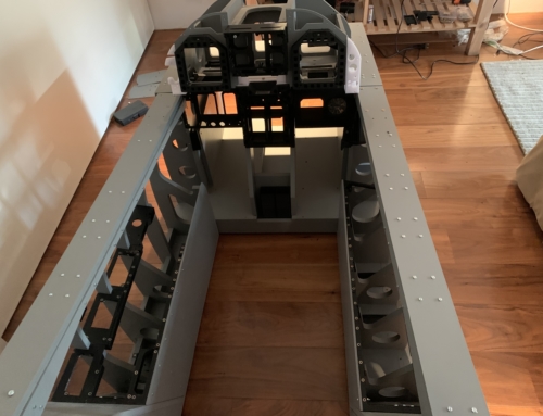
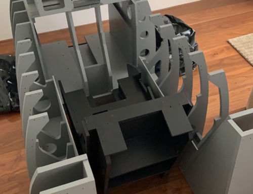
As I can’t dedicate a room for the pit it will need to be in storage when not in use. I had a choice between putting each section of the pit on wheels or mounting the whole thing on a platform. While both have their pros and cons I settled on the platform as it’s easier to move around and my wiring harness runs between sections so if I need to move the pit there would be quite a bit of unplugging to do. The platform is made from 20mm thick plywood which is cross braced underneath. I looked around for the biggest caster wheels I could find and put 5 of them on the platform. Four on the corners and one centered beneath the seat to support the weight of the pilot. The wheels are locking and quite large so moving the pit around is super easy. The main downside with mounting the pit on the platform is the added challenge of vibrationally isolating the seat from the platform so that the buttkicker can work effectively. I’m also looking at putting the seat on car rails so it can be moved back away from the stick to save yourself from accidental castration every time you get in.
Future:
I finally bit the bullet and got myself a resin printer. I picked up a Creality Halot One for $200.
My Prusa has been pumping out parts for the Left Aux and mechanisms. I have built the hook and park brake mechanisms, but I’ll cover that in the next one. This was all done with the kits provided from L.Walker on his site http://skysim.store
That’s all for now.


Leave a Reply