
Lazs’ Log #3 | More Printing, Wiring and Bodnars!
This build is based on pre-release files. It may not reflect the release build exactly.
OH Spec electronics have not been finalized and may change
Some small changes and modifications are anticipated.
Overview:
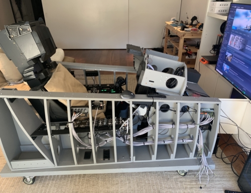
Since the last update, a lot of progress has been made. I’ve finished printing the consoles, wired up nearly all of my switches, and installed the Bondnar boards/Arduinos.
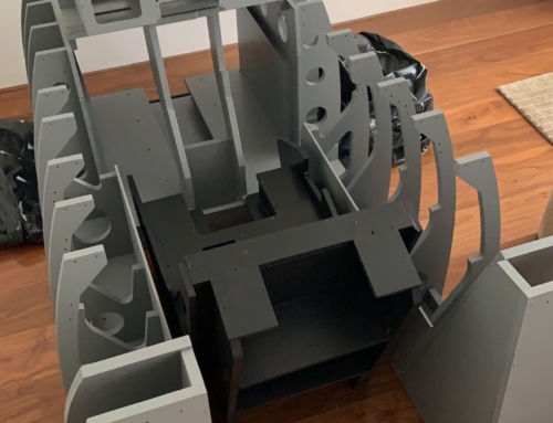
Console Printing and Threaded Inserts:
The consoles didn’t take too long to print. I printed using a .6 nozzle for all of the console parts. The finish from a .8 nozzle is a bit too rough for my liking, and .4 takes too long so .6 was a perfect in-between for me. There’s nothing wrong with printing with either and really it’s up to personal preference.
After installing all of the brackets into the consoles I began putting the threaded inserts in. The threaded inserts allow you to screw the panels into the consoles. To install the inserts I first put them on the end of a soldering iron and let them heat up for a few seconds, from there you just align it with the hole it’s meant to sit in and push with a bit of pressure until its almost flush with the plastic. Then pull out the soldering iron and, using something flat to push the insert in the last few mm.
Switches and Wiring:
A big thank you to L.Walker for helping me get all of the switches together. I used Octopart which automatically collates all of the switches into one basket. PM me or one of the OH Devs on discord for the link.
Most of my switches came from Digikey while the rest came from Mouser.
For wiring I’ve used a combination of 3 Core stranded wire and single core stranded wire. The wire is 0.25mm and I’ve got 200m of it. I have quite a bit of excess wire but its better to over-order than under.
Wiring up all of the switches is quite tedious but isn’t too much of a hassle. For 80% of the switches I used the 3 core wire as they have 3 prongs to connect to. There are a few that have between 8 and 24 connections so for those I used the single core wire.
I soldered each connection and then heat shrank them to prevent them shorting and help them last longer. Measure the distance to the switch and add on 15 cm of wire to have some slack for cable management.
The real pain in the ass is the DuPont connectors. These are what connect the switches to the Bodnars/Arduinos. Each one needs to be crimped to every wire and then inserted into a housing. Buy hundreds of those little bastards. They really are horrible to work with, especially the first few times. It does get easier with time but it takes a while to get used to them.
I learned the hard way that you should crimp to a 2×2 or 3×3 connector and not a 1×1 for every wire. They DO NOT stay on if you use a 1×1. Even if you have to waste a connection on the board, trust me its worth it.
Bodnars and Arduinos:
I’ve opted to go with a Bodnar board setup opposed to sticking everything through Arduinos. I did this mainly because I don’t solely fly the Hornet and whilst DCS Bios is awesome, I don’t want to have to flash the pit every time I want to change aircraft. The Bodnars allow a switch to be recognized as a generic joystick device meaning they can be used in any game and for any plane.
I’ve mounted a BBI-64 in the RC, LC and LIP. I’ve then got a BUO836X in the LC and UIP and then I also have 2 extra non X BUO836’s in case I run out of pot inputs.
Screens:
I also received my screens from Buydisplay. They look great! Be careful when installing them to not scratch them. I scratched one but luckily you can’t see the part with the scratch, still it’s quite a nasty gouge.
Conclusion:
The pit is finally coming along and is starting to resemble a F/A-18!
A massive thank you to the OH Dev team for making this possible and to L.Walker for guiding me though everything.
My Panels and Backlighting PCBs are en route from Australia courtesy of L.Walker and should be here in the next few days.
The next update will come very soon and will be all about putting together the panels!


Leave a Reply