


Hey all! It’s been a while. We are slowly chugging towards our beta release on the not-so-distant horizon, but we still have a ton to do before we get there.
A couple weeks ago, I had a number of exciting conversations that convinced me that redesigning the electronics layer was a good path forwards. So, we have been plugging away and we are wrapping up preliminary design of the core Arduino Based Simulator Interface System (ABSIS) 2.0.
We made a number of changes to simplify wiring, handle greater power requirements than originally planned, and (probably most exciting) support native backlighting in the OpenHornet pit.
The backlighting would not be possible without L. Walker’s hard work of the conceptual design and prototyping it.
We have designed the following PCBs to act as the core of the system:
- ABSIS Bus Master
- ABSIS Mega
- ABSIS Nano
- ABSIS Backlight Controller
- ABSIS ATX PSU Breakout
- ABSIS Solenoid Driver
Note that we still need to redesign all the “OH Specific” PCBs that do specialized functions within the pit, i.e. DDI, AMPCD, UFC, Caution Panel, EWIs, etc. This will be accomplished in parallel with the testing of ABSIS 2.0 core boards.
ABSIS is designed for DCS based pits, and utilizes DCS-BIOS as the software interface layer to drive the pit electronics via an RS485 bus utilizing the MAX487 IC.
ABSIS RS485 BUS MASTER 2.0

The ABSIS Bus Master utilizes 3x MAX487 ICs to act as a master device for up to three RS485 buses. Each of these combined power/data buses is referred to as the “ABSIS Bus”. It does not provide IO to the pit controls via direct interfacing with this PCB, however it utilizes slave devices to do so. It accepts power via an 8-pin MOLEX mini-fit connector. This PCB is effectively a shield for an Arduino Mega R3. This PCB interfaces to the simulator PC via USB.
ABSIS Mega
RS485 Slave Device/USB Standalone

The ABSIS Mega is the larger of the two I/O PCBs. This PCB is used to directly interface with simulator controls and pass data back and forth with the bus master. It is capable of accepting 51 digital inputs (11 of those being PWM) and 16 analog inputs (which can also be used as additional digital inputs if required.) It accepts a six pin mini-fit MOLEX connector for data/power from the bus master PCB.
ABSIS Nano
RS485 Slave Device/USB Standalone

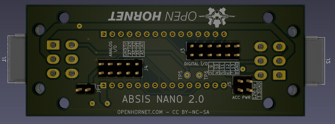
This is the ABSIS Nano, which will be the most common board through the OpenHornet pit. It accepts an Arduino Nano, and gives you 8 analog pins, and 11 digital inputs. It also uses the standard ABSIS data/power bus.
ABSIS Backlighting Controller

This gorgeous monstrosity acts as a shield on the Arduino Mega R3, and is powered by a 10-pin MOLEX power connector. It interfaces to the PC via USB, and supports 12 backlighting channels. Each channel consists of large strings of single-pin PWM-controlled RGB LEDs. Several analog/digital inputs are made available for controlling backlighting brightness, modes, turning on and off channels, whatever you want to program them to do. Look for an announcement regarding backlit OpenHornet panels in the very near future.
WARNING: She can suck a LOT of power. Don’t use anything but quality power supplies when supplying your pit or bad things may happen!
ABSIS Solenoid Driver Accessory PCB

This little beauty is a simple 6-channel MOSFET switch for driving higher voltage/amperage devices like the 12V solenoids commonly used throughout OpenHornet. She is the same form factor as the nano, so will stack neatly behind panels. Simply hook up a digital input (PWM compatible if you need it!) from the nano/mega, hook up your VIN, and hook up your solenoid or other device to the output channel, and you will be off and running!
ABSIS ATX PSU Breakout


This little guy breaks out your ATX PSU to the ABSIS PWR and BL PWR pinouts for ease of wiring and testing. Thanks CrazyCanuck for your work on this one.
If anyone has any questions, feel free to click above and join our discord and ask away!


Leave a Reply