
This tutorial was submitted by OpenHornet Dev Tester/Builder “Krikeee”.
Various instruments within the simulator (as denoted on their respective drawings, such as OHC007-1) requires a modification to allow the gauge stepper motor to have continuous travel. Fortunately, we can take the most common variants of these little stepper gauges and easily modify them, instead relying on external electronics to give zero position! The motor is the VID29-02P motor. Be careful, don’t use too much force, and take your time.
Tools & Materials Required
- VID29-02P Gauge Stepper Motor
- Small Philips head screwdriver
- Exacto/Hobby Knife with near Clear Blade
- Jeweler/Needle File
- Tweezers
Step 1: Housing Disassembly
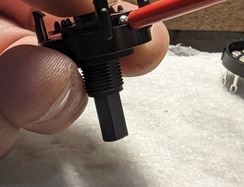
- On a soft surface, orient the stepper motor with the shaft side up (See Image 1)
- With the small screwdriver remove each of the four screws holding on the cover.
- Remove the cover being careful to not jar anything loose. It should come off easily leaving the shaft and gears visible. (See Image 2)

Image11

Image2
Be sure not to bend the pins on the underside of the motor.
Step 2: Shaft & Gear Removal

Image3

Image4
- Using the tweezers or your fingers, grasp the metal shaft and lift gently. It will pull up the gear it is attached to and it will slightly lift the gear on top of it.
- Slide the shaft and its gear out from beneath the top gear tilting it a bit if needed.(See Image 3 and 4)
Step 3: Rotation Stop Removal
- Using the hobby knife carefully remove the small stop on the underside of the shaft gear. (See Image 5)
- Removing small slices at a time seems to work better than trying to cut the entire bit off at once.
- When done, ensure there is a smooth surface where the stop was located (See Image 6)
ALTERNATIVELYT, YOU COULD use flush snips, razor blades, or even nail clippers OR JUST sand or file it down. Just ensure a clean, smooth surface to prevent additional friction, snagging, OR LOST MOTOR STEPS.

Image5

Image6
Step 4: Motor Reassembly

Image7
- Carefully replace the shaft and the attached gear by slipping it back under the top gear
- Lift as needed to get the shaft seated back into the hole.
- You can gently spin the gears to ensure they are all engaging correctly. Be careful not to dislodge them however.
- Slide the cover back over the shaft and ensure it is flush with the rest of the housing.
- Screw in the four screws and tighten. Be careful to not overtighten them. (See image 7)
- Label or otherwise mark the motor so you know it has been modified. (Since there will be no external indications of the modification.)

Leave a Reply